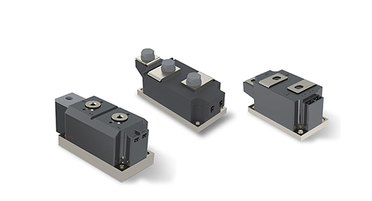
Detection method for diodes
Detecting low-power crystal diodes
A. Distinguish between positive and negative electrodes
(a) Query the symbol markings on the shell. Generally, the symbol of the diode is marked on the casing of the diode, with one end marked with a triangular arrow as the positive pole and the other end as the negative pole.
(b) Check the color dots on the shell. On the casing of a point contact diode, polarity color dots (white or red) are generally marked. The end marked with a color dot is usually the positive electrode. Some diodes are marked with colored rings, with one end of the colored ring being the negative electrode.
(c) The measurement with the smaller resistance value shall prevail, with the black probe connected to the positive terminal and the red probe connected to the negative terminal.
(d) Check the diode casing with a silver strip and one end as the negative terminal.
B. Detect high reverse breakdown voltage. As for AC power, due to constant changes, the highest reverse operating voltage is the peak AC voltage that the diode can withstand.
Detecting bidirectional trigger diodes
Place the multimeter in the corresponding DC voltage range. The inspection voltage is supplied by a megohmmeter. During inspection, shake the megohmmeter and measure the VBR value using the same method. Subsequently, VBO and VBR were compared, and the smaller the difference between the two values, the better the symmetry of the tested bidirectional trigger diode.
Detection of Transient Voltage Suppressing Diode (TVS)

A. Using a multimeter to measure the quality of a single pole TVS, the forward and reverse resistance can be measured using the same method as measuring a typical diode. The forward resistance is generally around 4k Ω, and the reverse resistance is infinite.
Regarding the TVS with bidirectional polarity, the resistance value between the two pins measured by freely swapping the red and black probes should be infinite. Otherwise, it indicates that the tube is not functioning properly or has been damaged.
Detection of high-frequency variable resistance diode
The difference in appearance between positive and negative high-frequency variable resistance diodes and general diodes is that their color codes are different. The color code for general diodes is generally black, while the color code for high-frequency variable resistance diodes is light. Its polarity pattern is similar to that of a general diode, where the end with a green ring is the negative electrode and the end without a green ring is the positive electrode.
Previous: No More
Next: Smart Home Device Shipments to Exceed 2.5 Billion in 2030


